| # of Ways | One-line Diagram (Horizontal) | Voltage Class (kV) | Mom. (kA asym) | Catalog Number | ||
| Width* in. (mm) | Wt. w/SF6 lbs (kg) | |||||
| 2 | 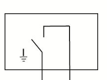 | 15 | 40 | T21-376F-40RP | 45 (1143) | 1400 (636) |
| 25 | T21-386F-40RP | |||||
| 35 | T21-396F-40RP | |||||
| 3 |  | 15 | 40 | T33-376F-40RP | 60 (1524) | 1600 (714) |
| 25 | T33-386F-40RP | |||||
| 35 | T33-396F-40RP | |||||
| 4 | 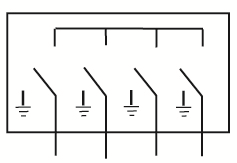 | 15 | 40 | T44-376F-40RP | 75 (1905) | 2100 (953) |
| 25 | T44-386F-40RP | |||||
| 35 | T44-396F-40RP | |||||
| 5 | 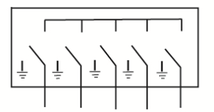 | 15 | 40 | T55-376F-40RP | 90 (2286) | 2300 (1044) |
| 25 | T55-386F-40RP | |||||
| 35 | T55-396F-40RP | |||||
| 6 | 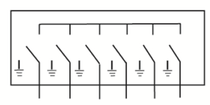 | 15 | 40 | T66-376F-40RP | 105 (2667) | 2750 (1250) |
| 25 | T66-386F-40RP | |||||
| 35 | T66-396F-40RP | |||||
| Approximate Enclosure Depth: 51.0" (1448mm). Approximate Height: 49.0" (1245mm) |
||||||
