Ryan Sales logo
(281) 363-1106
Home
TFI – Load Break Switching with Integral Ground and Fault Interrupting

TFI - Load Break Switching with Integral Ground and Fault Interrupting

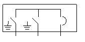
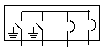
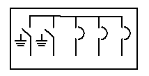
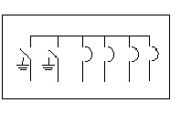
G&W Electric model TFI padmount switches include load break and fault interrupting capability. The load break switch features visible break and integral ground position. The integral ground position eliminates the need to handle any high voltage connections to ground the cable connected to the load break ways. The fault interrupters provide electronically controlled, resettable over current protection in a totally sealed, dead front device. The switches are designed for use on 3-phase systems with voltages up to 27kV, 630A load break, and continuous current, and 12.5kA symmetrical fault interrupting ratings. They feature compact footprints due to their front access construction.

The switches are designed to IEEE C37.72, C37.74, and C37.60 for load break and fault interrupting capability. Padmount enclosures are designed and tested to IEEE C57.12.28 and C57.12.29.

Features and Benefits

  • Construction – Available with front accessible switch operators and bushings or with front and back operators and bushings for replacement of existing pad mount air or oil insulated equipment. Vault construction is also available with top or bottom bushings or top access to operators and bushings.
  • Visible Break – Load break ways are equipped with visible break to view the open and closed positions.
  • Fault Interrupting – Three phase fault interrupting up to 12.5kA with selectable industry curves including fuse emulation curves.
  • Ground Position – Integral ground position on load break ways to eliminate the need to handle high voltage components to ground the cable.
  • Voltage Sensing – Load break ways are available with integral voltage sensing for use with voltage indication panel to determine in-phase condition or for use with a relay with up to 1% accuracy.
  • Automation – Available for motor automation with portable or permanently mounted motor and controls. A variety of relays such as SEL, ABB, and GE are available with G&W Electric programming and cabinet construction. Cabinets can be ordered in a low voltage enclosure for padmount, pedestal or IP68 rated submersible for vault installed switchgear. Programming for automatic source transfer, or LaZer custom solutions are available.
Configurations Chart for TFI

# of WaysOne-line Diagram (Horizontal)Voltage Class (kV)Catalog NumberApproximate
Width* in. (mm)Wt. w/SF6 lbs (kg)
6F
15TFI32-376-12-6F55.6 (1413)1350 (612)
25TFI32-386-12-6F
9F
15TFI42-376-12-9F68 (1727)2200 (1000)
25TFI42-386-12-9F
52F
15TFI52-376-12-52F76.1 (1934)2800 (1273)
25TFI52-386-12-52F
62F
15TFI62-376-12-62F95.2 (2417)3050 (1386)
25TFI62-386-12-62F92 (2337)
Approximate enclosure height: 50" (1270mm), Approximate depth: 55" (1307)

Configurations Chart for VTFI

# of WaysOne-line Diagram (Horizontal)Voltage Class (kV)Catalog Number
Approximate
Width* in. (mm)Wt. w/SF6 lbs (kg)
6F
15VTFI32-376-12-6F62 (1575)1350 (614)
25VTFI32-386-12-6F
9F
15VTFI42-376-12-9F74 (1880)1500 (681)
25VTFI42-386-12-9F
52F
15VTFI52-376-12-52F86 (2184)1750 (796)
25VTFI52-386-12-52F
62F
15VTFI62-376-12-62F98 (2489)1950 (886)
25VTFI62-386-12-62F
Approximate height of tank minus frame: 29" (737mm), Approximate depth: 25.5" (648)
Ratings Chart for TFI and VTFI

Voltage Class15kV25kV
Maximum design voltage15.5kV27kV
Impulse level (BIL)110kV125kV
One minute withstand35 AC kV60 AC kV
One minute withstand, production test rating34 AC kV40 AC kV
15 minute withstand53 DC kV78 DC kV
Continuous and load break current630 Amps630 Amps
Momentary current40kA asym40kA asym
Fault close current, (3 times)32kA asym32kA asym
One second current25kA asym25kA asym
Fault interrupting ratings12.5kA sym12.5kA sym
Mechanical endurance, operations20002000
IEEE C37.60 Fault Interrupting Duty
Total number of fault interruptions: 116
Percent of Maximum Interrupting RatingApprox. Interrupting Current, AmpsNo. of Fault Interruptions
15 – 20%2,00044
45 – 55%6,00056
90 – 100%12,50016